
Note: You are viewing an old revision of this page. View the current version.
This article was submitted by KonZissis.
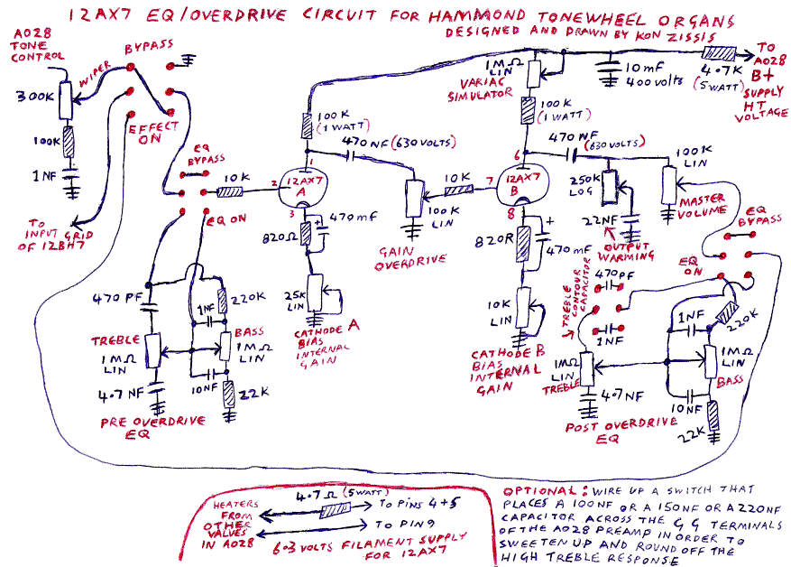
My ?previous 12AX7 based EQ and overdrive circuit was located after the G-G output terminals of the AO-28 preamp because I was able to get a better bass growl and crunch from this location compared to the lesser bass growl and crunch that was previously available if the circuit was placed between the tone control wiper and the input grid of the ?12BH7 output valve.
One major problem with the previous EQ/overdrive circuit that was located after the G-G output terminals was that an expensive output coupling transformer was required that would split the output signal into a dual balanced line output so that the output signal could be properly matched with a balanced line Leslie such as the 122 or a HammondToneCabinet.
More recently I have experimented with and I found a way to get the nice bass growl and crunch with the EQ/overdrive circuit being located between the tone control wiper and the input grid of the 12BH7. The reason why the bass response was being rolled off in my earlier 12AX7 EQ/overdrive circuit design that was located between the tone control wiper and the input grid of the 12BH7 was that the impedance to ground of the input gain control that fed the signal into the first gain stage of the ?12AX7 valve would cause the lower bass frequencies to be rolled off from the signal coming from the tone control wiper. The tone control wiper needs an extremely high impedance in order to allow the full bass response to pass and even using a 1 Meg ohm pot as an input gain control causes some of the lower bass frequencies to roll off. I overcame the bass roll off problem by not wiring any input gain control between the tone control wiper and the input grid of the 12AX7 and just having the passive bass and treble EQ wired between the tone control wiper and the 12AX7 input grid.
I did a careful A/B listening test with the 12AX7 EQ/overdrive circuit switched in and out of circuit and with the gain/overdrive control set to a low level to produce the pure clean sound and the master volume control set to the full volume setting so that the volume level of the organ through the EQ/overdrive circuit was identical to that of the fully bypassed organ signal. After doing this careful A/B listening test, I verified that with the EQ controls set to the flat setting, the tonal response of the organ is identical and without any bass roll-off. Because of this the newly revised circuit is now simpler and cheaper to build than the version that was located after the GG output terminals and that needed the output coupling transformer. The quality of the overdrive tone is very good and it does sound similar to an overdriven Leslie 122 or a 147 valve amplifier depending on the settings of the EQ.
This circuit is reasonably simple in operation in that it uses one 12AX7 valve and a passive bass and treble EQ before the gain/overdrive stage and also a passive bass and treble EQ after the overdrive stage. Both EQ's can be activated or bypassed with a 2-pole / 2-position (DPDT) switch.
The passive bass and treble EQ's are _Baxandall_ type EQ's and I have simply copied the bass and treble tone stack that BobSchleicher
displays on the  schematics section of his website (see
  http://www.tonewheel.com/Schematics/tonecontrol.jpg),
however I have disregarded the low gain cathode follower circuitry that BobSchleicher's circuit uses and I have simply wired the EQ tone stack
before the input grid and after the master volume control of the EQ/overdrive circuit.
http://www.tonewheel.com/Schematics/tonecontrol.jpg),
however I have disregarded the low gain cathode follower circuitry that BobSchleicher's circuit uses and I have simply wired the EQ tone stack
before the input grid and after the master volume control of the EQ/overdrive circuit.
The pre-overdrive EQ affects the tonality of the signal going into the 12AX7 valve. This is useful if your organ has a weak bass response and you want more of a bass growl and grind or if you want more distortion from the organ treble frequencies.
The post-overdrive EQ shapes the sound after it has passed through the overdrive stage. This can give you a nice fat bass but without distortion because it is located after the gain/overdrive stage. You can simulate the deeper bass response of a Leslie connected together with a PR-40 Hammond tone cabinet.
There is an additional modification to the treble capacitor of the post overdrive EQ treble control. You can use a DPDT switch to select either the original 470 picofarad (pf) capacitor or a 1 nanofarad (nf) capacitor. The 470 pf capacitor produces the true flat response sound when bass and treble are set to the _"flat"_ position. For the bass control, the _"flat"_ setting is the 12 o'clock position and for the treble control the _"flat"_ position is at around the 2 o'clock position.
With the 470 pf capacitor, turning the treble control to the full position results in the higher treble frequencies being emphasised thus making the distortion more raspy sounding. When the 1 nf capacitor is chosen there is a discernible increase in the lower midrange warmth when the treble control is set at the "flat"_ 2 o'clock position and when you turn the treble control to the full position the upper midrange as well as the treble is emphasized for more presence and _"scream". This can be useful if you have a muddy sounding Leslie or a Hammond tone cabinet or an external amplifier or speakers. If you want to you can add this same capacitor switching option to the pre overdrive EQ treble control.
I recommend that both EQ's are left on because when they are bypassed the organ signal levels will be extremely high and there will always be some distortion in the first gain stage of the 12AX7 if the pre-overdrive EQ was bypassed. With the pre-overdrive EQ switched on, you can get a fully clean sound even with the expression pedal at the full volume position when the gain/overdrive control is set at a low setting. Setting the gain/overdrive control to the fully clockwise position will produce a heavy JonLord level of overdrive.
The two cathode bias internal gain pots determine the total internal gain level of the two gain stages of the 12AX7 valve. In my own circuit in my 1963 C3 l have found that the best sounding overdrive tone is created when the 25 K ohms cathode gain control of the 12AX7 gain stage 1 is set at slightly less than the full position. I have the 10 K ohms cathode gain control of the 12AX7 gain stage 2 set at the full gain position. If both cathode gain controls are set to the fully clockwise position for maximum gain then the distortion has a harder sounding quality to it but when the cathode gain control pot of the 12AX7 gain stage 1 is set at slightly less than the full position such as between the 3 o'clock and the 4 o'clock position , the valve breathes better and the distortion sounds more natural. The trick is to set the cathode bias internal gain controls to the setting that produces the maximum amount of distortion that you want when the gain / overdrive control is set to the fully clockwise setting. If you only like a mild distortion , then you can set the 25 K ohms cathode bias gain control of the gain stage 1 to a lower setting so that when the gain / overdrive control is set to the fully clockwise position there will only be a milder level of distortion.
Next to the 100 k ohms plate resistor of the second gain stage of the 12AX7, there is a 1 M ohms pot wired in series and it is labeled as "Variac simulator". This 1 M pot can lower the HT voltage going to the second stage of the 12AX7 valve in order to starve the plate of the second gain stage for a very squashed and dirty sound if this is desired. When it is set to the fully clockwise position, the full HT voltage goes to the plate B for the loudest output level. Even with this setting you can still get a full overdrive sound when the gain overdrive control is set to the fully clockwise position.
After the signal has passed out of the second stage of the 12AX7 it goes to the output warming control. This is basically a passive high cut control similar to a passive tone control but there is a sweet spot setting at lower end of the range at around 9 o'clock where there is the effect of a bottom boost which adds depth to the sound and the top end of the distortion is smoothed out for a sweeter, more vintage sounding overdrive effect because this output warming control brings a grounding 22 nf capacitor to the signal coming from the plate of the 12AX7 valve and it affects the way that the treble distorts when the second stage of the 12AX7 valve is overdriven. I normally play my 1963 C3 in my room at a comfortable volume level and at these mild volume levels , setting the output warming control to the 9 o'clock position produces a very nice sounding chunky bottom end combined with a sweeter overdrive tone that sounds very pleasant. If you do set the output warming control to the 9 o'clock position then setting the post overdrive EQ bass control down to around the 9 o'clock position will produce a more or less flat bass response . All of this is a matter of personal taste , the actual Leslie or external amplifier that the organ is being played through and the room acoustics.
BY THE WAY, although I have specified a 22 nf capacitor on the output warming control , you can experiment with other capacitor values to get the type of sound that you like. I have added a 1 pole , 12 position rotary switch with the following capacitor values : 1 nf , 2.2 nf . 3.3 nf , 4.7 nf , 5.6 nf , 8.2 nf , 10 nf , 15 nf , 22 nf , 33 nf , 47 nf , and 82 nf.
This variable capacitors rotary switch adds a lot of flexibility to the output warming effect of the overdrive sound.
If you have a modern treble driver such as the Hammond Suzuki 100 watt ferro fluid driver that is too bright sounding in your Leslie , you can turn down the output warming control to compensate for this.
After the output warming control there is the master volume control and after this there is the passive post overdrive EQ bass and treble controls. Set the amount of overdrive that you want with the setting of the expression pedal and the gain/overdrive control and then set the master volume to what ever listening volume level that you like.
An optional wiring modification is to add a sweetening switch that brings either a 100 nf or a 150 nf or a 220 nf capacitor across the G-G output terminals of the AO-28 preamp. Even though the 12AX7 EQ/overdrive circuit is not connected to the G-G output terminals of the AO-28, the audio signal in the organ passes through the G-G outputs before going to the Leslie or the tone cabinet and consequently the sweetening capacitor wired across the G-G outputs will result in a sweeter, more rounded out treble response which will make the treble harmonics of the overdrive effect sound sweeter because any fizzy sounding higher harmonics of the overdrive effect are rolled off. The sweetening switch and the actual capacitor nf value chosen is also a matter of personal taste. I like the sweetened sound when the 150 nf or the 220 nf capacitor is switched across the G-G output terminals.
Also see ?KonsZenerDiodeBasedOverdriveCircuit.
The content of this page is Copyright (C) 2000, 2001, 2002 Geoffrey T. Dairiki and
the other authors of the content, whoever they may be.
This is free information and you are welcome redistribute it
under certain conditions; see
http://www.dairiki.org/HammondWiki/opl.html for details.
Absolutely no warrantee is made as to the correctness of
the information on this page.