Title: Repair and Disassembly of Vibrato Scanners

Although this technical bulletin is based on scanner repair, it is not the single source of vibrato problems. Check existing switches, vibrato pre-amp. (tubes, etc), phase shift line box, and cables both to and from the scanner.

Symptom Cause Repair
Dead Vibrato SwitchReplace Switch
Vibrato pre-amp. (Tubes, etc.) Replace tubes or other defective components.
Open Signal Wire to Line-box Replace wires or repair connections.
Open From Scanner shielded cable.
Choppy Vibrato Shorted capacitors on line-box Replace defective components
Open coils on line box
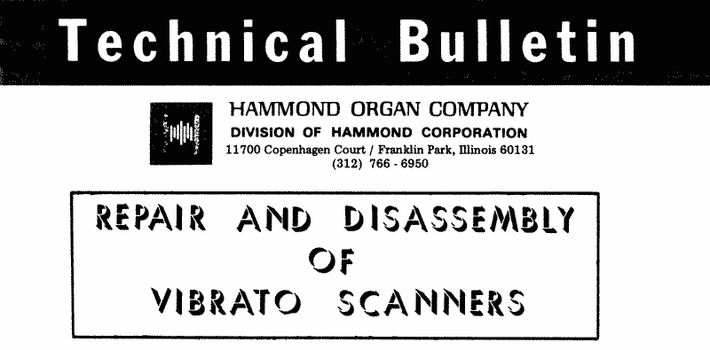
Oil saturated Bakelite insulators which pick up impurities and short out the stationary plates to the main assembly chassis of scanner. Clean stationary and rotor plates and replace insulators, isolating the stationary plates from the main chassis.
Rotor plates rubbing against the stationary plates inside scanner. Check end play and height of rotor on gear and shaft assembly.
Slow Vibrato Semi-frozen bearing on gear and shaft assembly Check oiling threads and for proper oiling.
Poor tension on drive springs of the gear and shaft assembly. Replace gear and shaft assembly.
No Vibrato Frozen bearing on gear and shaft assembly Replace gear and shaft assembly.
Squeaking Sound. Tension springs of the carbon brushes mispositioned causing the brushes to make a squeaking sound against the rotor contact pins. Heat spring connection with soldering iron and spring will fall into its proper position.
Dry bearings Check for proper oiling.

Scanner Removal, Disassembly and Repair Procedure

  1. Detach motor and scanner assembly (A) from the generator assembly by removing four (4) nuts from the synchronous motor which anchors the motor to the "L" brackets of the generator assembly.
  2. Remove the cable connections in the organ so motor and scanner assembly is free from organ.
  3. Note A.C., line box, and output connections for reassembly.
  4. Locate oil cup (B) and oil felt (C) inside cup. The oil felt must be removed and the cotton threads unwrapped from the felt before separating the scanner and motor. Remove felt retainer spring (D) and lift up on the felt to remove the threads. (Do this very carefully to avoid breaking the cotton threads). After removing the threads from the oil felt take a pick or a paper clip and remove the three threads from the one side of the oil cup by pulling them through the hole in the cup. The thread from the other side of the cup need not be removed.
  5. Locate screws (E) which hold the motor and scanner assembly together. Remove the screws and pull the motor and scanner assembly apart. Note: There is a gear on the end of the motor shaft and must be guided through the hole of the scanner housing to separate the motor and scanner.
  6. Remove two screws (F) from the rear cover (G) of the scanner. Before removing the cover note that there is a shielded wire attached to the cover. This wire is connected inside the scanner and there is very little slack in the wire. Remove the cover and tip it back carefully so you can see inside. Locate the carbon brush audio pick-up assembly (J). The carbon brushes must be removed before the main housing assembly cover (M) is removed, in order to prevent damage to the carbon brushes and tension springs. Lift end brush (I) and slip the two carbon brushes (H) off the rotor contact pin. (Be extremely careful of the rotor contact pin during disassembly so that you do not bend or break the pin).
    Figure 1
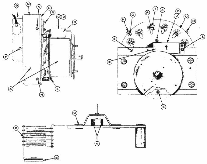
    Should it be necessary to remove the carbon brush audio pick-up assembly (J), desolder the audio wire from the brush assembly and remove the two (2) screws (K). To remove the end brush (I) remove screw (L) and separate from the brush assembly.
  7. Remove the four (4) screws (N) and slip the housing cover (M) off the main assembly. Note: Mark the housing cover (M) and the main assembly chassis (U) to indicate the starting point of the scanner cable, also mark the location of the cable clip (O).
  8. Stationary plates (P) and rotor (Q) are mounted on the main assembly chassis (U). Remove two (2) of the stationary plates (P), by removing screws (R). When removing the stationary plates from the assembly you will notice that there are insulator (S) and (T) on both sides of the main assembly chassis, insulating the stationary plates from the assembly (U). Then remove the rotor assembly (Q) by loosening the two (2) Bristol type set screws (V), to avoid damaging the rotor contact pin during disassembly.
  9. Remove the remaining (14) stationary plates and insulators.
  10. Clean the stationary plates, rotor plates and other metal parts using a Freon spray or other cleaning solvents that do not leave any residue after drying. An absorbent cloth or swab can be used in conjunction with the cleaner.
  11. Spray metal coated parts with Krylon Corona Dope (clear). Caution: Do not allow spray to get on oil threads or rotor pick-up pin.
  12. In most scanner repair you need not go further in disassembly than step number eleven (11) but should conditions warrant further disassembly continue with number thirteen (13), otherwise install new insulators and reassemble the scanner.
  13. In removing the gear housing assembly (W) there are four (4) screws (X) holding the assembly on to the main assembly chassis (U). Upon removing the gear housing assembly you will notice the Bakelite gear and shaft assembly (Y). The springs on either side of the Bakelite gear also intermeshes with the metal gear of the synchronous motor to drive the scanner.
  14. To reassemble the scanner reverse this procedure.
    Figure 2

Transcribed July 16, 2001 by Geoffrey T. Dairiki from scans by Steffan Diedrichsen.

See also HammondWiki:HowToRebuildTheVibratoScanner.