Note: You are viewing an old revision of this page. View the current version.
In a Hammond, the "chorus" effect is generated by mixing the "vibrato" signal with the straight or "dry" signal. The amount of vibrato signal included in the mixture is referred to as the chorus depth.
In a stock Hammond, the chorus depth is set by a fixed resistor (R44 in an AO-28 organ). (The lower the resistance, the greater the depth of chorus.) It is interesting to note that different organs use different values for the chorus depth resistor --- in particular, A-100's typically have deeper chorus than B-3's.
A common modification is to replace or augment the chorus depth resistor with a potentiometer so that the chorus depth may be varied.
The following write-up on the modification was written by BradBaker. (This write-up describes a fixed chorus modification, but the variable chorus modification follows an obvious extension of this procedure.)
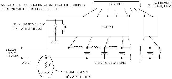
Here's a simple modification that will increase the depth of the chorus effect on tonewheel Hammonds. All it takes to do this modification is a resistor, the value will be between 15k to 75k or so - depending on how it sounds to you - and a couple of feet of hookup wire. To do the modification you will solder a resistor to one of the pins on the vibrato delay line. The other end of the resistor will go to a convenient ground in the system somewhere, to a lug under one of the preamp chassis securing screws for example. Referring to the first figure,the depth of the chorus on unmodified organs is set by the value of the resistor located inside the vibrato switch assembly. The vibrato switch assembly is the long metal box under the drawbar base that has the rotary chorus/vibrato knob emerging perpendicularly and at one end. The chorus effect is created by summing the vibrato'd with non-vibrato'd signals across this resistor.
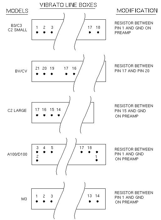
The value of this resistor can be reduced by paralleling another resistor with it - at the vibrato line box - not inside the switch assembly. The new resistor is externally mounted to the pins on the vibrato delay line as indicated in the second figure under the "Modifications" column. If your chorus is too deep (too much vibrato), you'll have to increase the value of the resistor inside the switch. This will require disassembly of the switch to change out the resistor with one of a higher value. 68 kilo-ohms ought to do it.

The vibrato line boxes on the different models are somewhat different. While they have similar topologies, they differ in numbers of components, impedance, etc.. Before you actually solder anything in place, you might want to experiment with the amount of vibrato mix. Parallel a 100k potentiometer, wired as a rheostat, to the pins indicated on the second figure. If you need a ground to the preamp, run a wire to the preamp chassis somewhere. Tweak the rheostat until things sound nice and either replace it with a fixed value or just leave it in place.
I've tried this mod only on one of the models shown above. On all of the other models, I got the pinouts from looking at the service manual and schematics.
I'm interested in getting some feedback from those of you that try this out. BradBaker.

The content of this page is Copyright (C) 2000, 2001, 2002 Geoffrey T. Dairiki and
the other authors of the content, whoever they may be.
This is free information and you are welcome redistribute it
under certain conditions; see
http://www.dairiki.org/HammondWiki/opl.html for details.
Absolutely no warrantee is made as to the correctness of
the information on this page.